Arduino API
Example TLE9562_DCM-control
Here we go through each function and variable used in this sketch and show up other control possibilities.
void setup()
Include the library and create an instance of the class DCMcontrolIno:
#include <Arduino.h>
#include <DCM-control-ino.hpp>

#define MOTOR_OUTPUT            3            // [1;3]
#define SPEED_INCREASE_STEP     100          // [1;511] speed step increase/decrease when pressing a key

uint16_t speed = 400;
uint8_t direction = 0;

// Create an instance of DCMcontrol called 'MyMotor'.
DCMcontrolIno MyMotor = DCMcontrolIno();
The MOTOR_OUTPUT define is used to configure which motor will be controlled according to the table below. Motor 1 has to be wired to PHASE1 and PHASE2, Motor 2 to PHASE3 and PHASE4.
MOTOR_OUTPUT |
Motor 1 |
Motor 2 |
|---|---|---|
1 |
yes |
no |
2 |
no |
yes |
3 |
yes |
yes |
The not-controlled motor will always keep its last state.
Now set up a GPIO interrupt routine bound to Pin 2 (the interrupt Pin of the TLE956x shield). By default, the library configures the TLE to throw an interrupt if an error in one or more status register occurs:
// Enable GPIO interrupt for pin 2
attachInterrupt(digitalPinToInterrupt(2), TLEinterrupt, LOW);
When you jump to the last lines in the example sketch, you see, the TLEinterrupt function only sets the variable interrupt_status_changed to one. Just keep that in mind for now, we come to the reason later on.
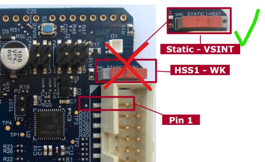
Important note: In order to use the interrupt function properly, make sure the HSS switch of the board is in position Static. Otherwise the interrupt is bound to the PWM of HSS1 and thus called periodically, if this HSS is used.
Next initialize the pins and configure the interrupt mask (which TLE956x-errors cause an error message on the serial monitor). The default settings will be applied. The TLE9562 DC motor shield also features two red LEDs that can be controlled individually by using two HSS outputs of the TLE9562. Using the setLED() function, the brightness of both LEDs can be set using a 10-bit value:
MyMotor.begin();
MyMotor.configDCshield();
MyMotor.setLED(0,100);                                                 // Switch on LED 2
At the end of the setup() function, the initial set speed and direction for the selected motor(s) will be applied to the shield:
MyMotor.setDCspeed(speed, direction, MOTOR_OUTPUT);
MyMotor.startDCM();
void loop()
In order to change speed, direction, motor outputs, start or stop the motor, an if-routine has been implemented, that scans the Serial-input line. Have a look in Keyboard commands to see which key to press:
if (Serial.available() > 0)
{
        uint8_t in = Serial.read();
        if(in == '+')
        {
        speed += SPEED_INCREASE_STEP;
        Serial.println(speed);
        }
        if(in == '-')
        {
        speed -= SPEED_INCREASE_STEP;
        Serial.println(speed);
        }
        if(in == 'd')
        {
        direction = 0;
        Serial.println(F("forward"));
        }
        if(in == 'e')
        {
        direction = 1;
        Serial.println(F("backward"));
        }
        if(in == 'a')
        {
        MyMotor.stopDCM(BRAKEMODE_PASSIVE);
        Serial.println(F("Motor stopped"));
        }
        if(in == 'q')
        {
        MyMotor.startDCM();
        Serial.println(F("Motor started"));
        }

        MyMotor.setDCspeed(speed, direction, MOTOR_OUTPUT);
}
If a key was pressed, the changes will be applied to the board using the setDCspeed(speed, direction, MOTOR_OUTPUT) function again.
Example TLE9563_BLDCM-control
Here we go through each function and variable used in this sketch and show up other control possibilities.
void setup()
Include the library and create an instance of the class BLDCMcontrolIno:
#include <Arduino.h>
#include <BLDCM-control-ino.hpp>

uint16_t speed = 400;
uint8_t direction = 0;
uint8_t weakening = 0;

// Create an instance of BLDCMcontrolIno called 'MyMotor'.
BLDCMcontrolIno MyMotor = BLDCMcontrolIno();
Set up a GPIO interrupt routine bound to Pin 2 (the interrupt Pin of the TLE956x shield). By default, the library configures the TLE to throw an interrupt if an error in one or more status register occurs:
// Enable GPIO interrupt for pin 2
attachInterrupt(digitalPinToInterrupt(2), TLEinterrupt, LOW);
When you jump to the last lines in the example sketch, you see, the TLEinterrupt function only sets the variable interrupt_status_changed to one. Just keep that in mind for now, we come to the reason later on.
Important note: In order to use the interrupt function properly, make sure the HSS switch of the board is in position Static. Otherwise the interrupt is bound to the PWM of HSS1 and thus called periodically, if this HSS is used (e.g. the green LED is on).
Motor control functions
First, we need to call the begin() function, that configures all input/output pins, PWM frequencies and so on. The function setLED(red, green, blue) let us set the color of the onboard RGB-LED, driven by the high-side-switches of the TLE. It takes 10-bit values as argument, so you can enter values from 0 (off) to 1024 (max brightness). Make sure your HSS-jumpers are in place.
MyMotor.begin();
MyMotor.setLED(0,20,0);
Now comes the important part: You need to select which position-feedback and which speedmode you want to use:
MyMotor.MotorParam.feedbackmode = BLDCMcontrol::BLDC_HALL;
MyMotor.MotorParam.speedmode = BLDCMcontrol::BLDC_BLDC_DUTYCYCLE;
MyMotor.MotorParam.MotorPolepairs = 4;
MotorParam |
type |
arguments |
input range |
|---|---|---|---|
feedbackmode |
mandatory |
BLDC_HALL |
|
BLDC_BEMF |
|||
speedmode |
mandatory |
BLDC_DUTYCYCLE |
0 - 1023 |
BLDC_RPM |
0- 2E32 |
||
MotorPolepairs |
mandatory for BLDC_RPM |
integer value |
0-255 |
PI_reg_P |
optional (default = 0.01) |
float value |
|
PI_reg_I |
optional (default = 0.01) |
float value |
If you don’t know the amount of pole-pairs in your BLDC, you can use the find_polepairs_BLDCM.ino sketch provided in the examples folder. If you use a wrong number, your actual RPM-speed might be imprecise.
In order to actually set the previous defined parameters, call the following function:
MyMotor.configBLDCshield();
Finally, we can set our default speed and direction and start the BLDC motor:
MyMotor.setBLDCspeed(speed, direction);
MyMotor.startBLDCM();
Depending on your configuration above, the speed - parameter will be interpreted as a percentage-value (a permil-value to be precise) or as a desired RPM-speed. direction can be 0 or 1. A third argument weakening range would be possible as well that can be 0 (default) or 1, but is only applicable if BLDC_HALL was selected. weakening range uses a different commutation pattern, that let’s the motor turn with its double speed but less torque.
startBLDCM() applies an open-loop commutation to your motor and enables the usage of serveBLDCshield() which actually commutates the motor.
void loop()
In order to change speed, direction, weakening range (only for BLDC_HALL), start or stop the motor, an if-routine has been implemented, that scans the Serial-input line. Have a look in Keyboard commands to see which key to press:
if (Serial.available() > 0)
{
        uint8_t in = Serial.read();
        if(in == '+'){
        speed += SPEED_INCREASE_STEP;
        Serial.println(speed);}
        if(in == '-'){
        speed -= SPEED_INCREASE_STEP;
        Serial.println(speed);}
        if(in == 'd'){
        direction = 0;
        Serial.println(F("forward"));}
        if(in == 'e'){
        direction = 1;
        Serial.println(F("backward"));}
        if(in == 's'){
        weakening = 0;
        Serial.println(F("Field weakening disabled"));}
        if(in == 'w'){
        weakening = 1;
        Serial.println(F("Field weakening enabled"));}
        if(in == 'a'){
        MyMotor.stopBLDCM(BRAKEMODE_PASSIVE);
        Serial.println(F("Motor stopped"));}
        if(in == 'q'){
        MyMotor.startBLDCM();
        Serial.println(F("Motor started"));}
        MyMotor.setBLDCspeed(speed, direction, weakening);
}
For example, if you press a, the function stopBLDCM(brakemode) is called. As the name says, it stops the commutation and prohibits the use of serveBLDCshield(), where brakemode defines, wether the phases are left floating (BRAKEMODE_PASSIVE) or actively tied to ground (BRAKEMODE_ACTIVE). The F() function which wraps the strings in the serial prints is called the F-macro and helps to save dynamic memory.
Last but not least, you may not forget to call the most important function, where all the magic happens: serveBLDCshield()
Depending on the previously defined configuration, this function checks, if the hall-sensor or BEMF-sensor state changed since the last time the function was called and if so, it commutates the output phases. This means, this function needs to be called as often as possible and the time between calling this function must be as short as possible.
MyMotor.serveBLDCshield();                // MUST BE CALLED HERE. This function does the BLDC commutation.
if(MyMotor.checkTLEshield() )            // Check, if interrupt flag was set and read status register of TLE
{
        MyMotor.setLED(50,0,0);                 // Set onboard RGB-LED to red.
}
The function checkBLDCshield() is not mandatory to run the BLDC, but handles error codes and prints debug messages. If you remind the interrupt setting at the beginning, I can now tell you, this function will only be executed if interrupt_status_changed was set to 1.